The Southern California Railway
"From the Mountains to the Desert to the Sea."
Background | Concept | Construction | Wiring-Control | Signaling & CTC | Operations | Gallery
Signaling & CTC
I am not an electronics guy. But electronics is the key to a fully functional signal system, which in my case was an absolutely essential element on the mainline of my model railroad. Fortunately Bruce Chubb has created a workable system using a computer to drive a signal system he dubbed a Computer-Model Railroad Interface or C-MRI.
I designed a signal system layout for the mainlines and for about two years I patiently wired the mainlines for block occupancy and line side signals using the Chubb documentation as a guide as well as talking to others who had gone down this path before including Lee Nicholas, Mike Burgett and Don Wood.
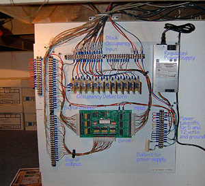
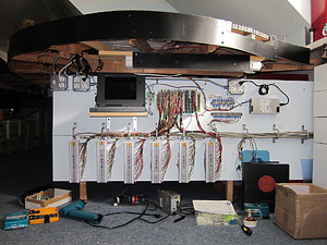
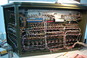
A series of sub panels were created to simplify wiring. Clean and clearly-marked cable management was essential. A series of data sheets was created to clearly show where each connection was and what it was for. These went through many revisions as the wiring developed.
At one point after some disappointments (code for smoked transistors) I made a careful study with the help of Don Wood as to what constitutes "basic ground." In this I learned that -12 and basic ground are not the same!
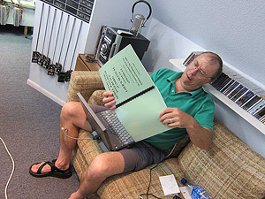
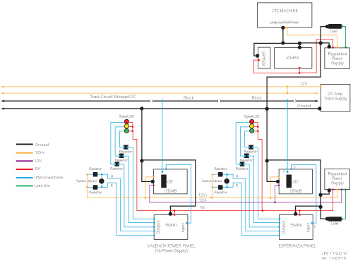
Surplus computer power supplies from an internet electronics supplier were purchased to power 5 Chubb-designed SMINI hubs strategically placed around the layout. Chubb-designed occupancy detectors were used throughout. With these in place, all that was needed was a four-wire cable to the computer, which is an old 1989 era laptop (courtesy Jeff Forbis and the McCloud Railway) with a DOS operating system and Basic language installed.
The Signals
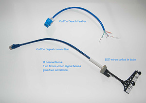
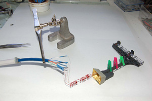
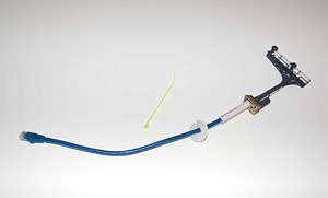
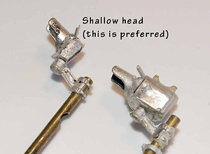
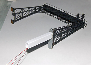
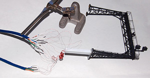
It is a sad state of affairs in the hobby that scale, prototypical and reliable signals have not been available with any consistency until recently. I had previously acquired a number of Sunrise Enterprises searchlight signals (with bi-color LEDS), but not enough to completely equip the layout, as well as a number of cantilever signal bridges. Jim Hinds at Richmond Controls had developed a tri-color LED for signal applications and I acquired a number of these. I drilled out the brass investment castings in the signal bridges enough to fit the LEDs and disassembled the Sunrise Enterprises signals by soaking them in nail polish remover then reinstalled tri-light LEDs in the signal heads. The accompanying photos show how I managed the wires leading from these signals.
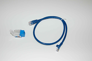
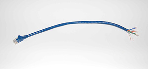
I used cat5e 8-wire cable to hook up all signals and signal lead wires on the system (on the advice of Photo Bob) in a consistent manner. This allowed for bench testing of each unit before installation after which they were mounted and plugged in on the layout.
Towards the end of the work, I ran out of Sunrise signals and experimented with BLMA signal heads, which work fine and I would recommend them for all but the signal bridge applications as the leads are not long enough. I specified 15-inch leads with the Richmond Controls LEDS.
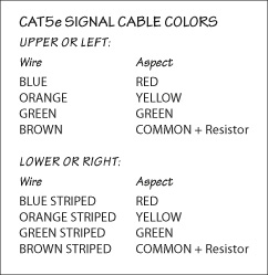 Cat5e Cable Diagram |
|
The Machine
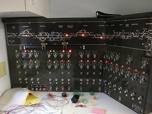
During the late 1980s and early 1990s, Rod Loder and I were able to secure a number of retired US&S CTC machines from the Southern Pacific and elsewhere. These were stripped of parts, cleaned and repurposed for not only model railroad use, but certain prototype applications. I designed CTC model boards in a computer application called Adobe Illustrator and these were output to a photo etcher. In the meantime, Rod had an original cabinet cut down and repainted and then assembled and wired the machine. Because of the requirements of my train room, we opted for a cut-down machine and ran cabling from it to telephone punch blocks underneath the layout where the computer interface was located.
Making It All Work
At this point, I was at a loss as to how to proceed. I approached long time friend Marty Nile, who is a Silicon Valley computer programmer by trade, to give me a few pointers as to the Chubb sample codes. A few months later, after he and Dennis Engdahl told me to just stand back and let them handle it, we were up and running. Marty elected to use the Chubb protocol and as of this writing we are on version 1.44 of the software running the CTC system. For those inclined we have included the latest code, operating manual and other items relating to the software driving the CTC system.
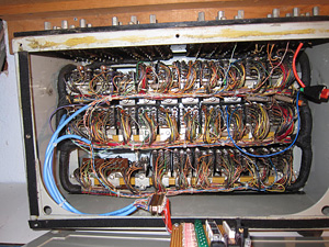
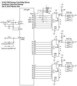
To replicate the sound of the CTC machine at work, Marty rewired all the relays in an actual US&S relay box and built a microcontroller to drive them to simulate the US&S 506 CTC codes. The controller is designed around the Atmel ATMega88 processor. The program is written in C using the WinAVR GCC compiler. He hand built the controller using old fashioned wire-wrap and point to point wiring.The microcontroller fits inside the back of the box behind the relays. The relay box is connected to the CMRI ports that drive the code and indication lamps on the CTC machine, so whenever the machine is "sending" or "receiving" a code, the box clatters along. It clatters like the real thing, but somebody who knows what the real thing sounds like won't be fooled. We have attached the source code for the program running on the microcontroller.
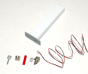
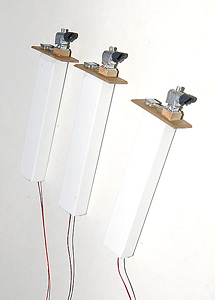
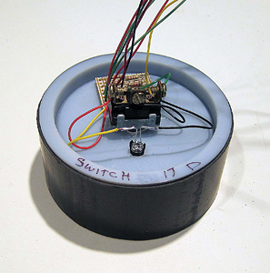
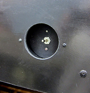
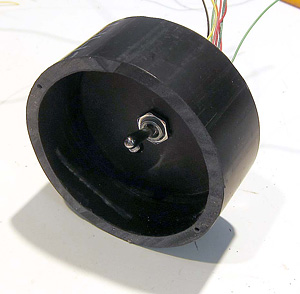
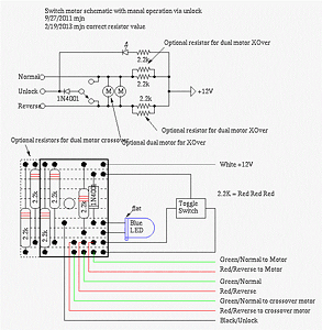
In any CTC system, access to the mainline is controlled either by signal indication or in some cases unlocks to hand-throw switches. At all OS sections and at several line side spurs, we opted for simplified unlocks which control which, when power is released from the dispatcher, a blue LED illuminates and it is possible for an operator to control the turnout by a toggle switch. The housing for these are made out of PVC pipe with end caps and are recessed in the fascia where a hole saw was used to make an opening.
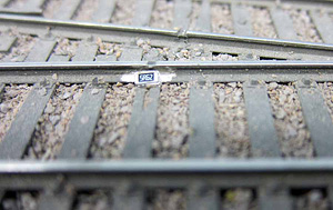
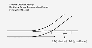
In more complicated areas, within yard limits, we opted for simple occupancy if a switch leading to the mainline was thrown by means of a miniature surface-mount resistor attached to the web of the rail behind the frog at a gap. Secured with ACC, conductive paint was used to complete the circuit across the gap. When the switch is shown, power flows through the resistor showing that the switch has been thrown. Signals cannot be cleared in that block until the switch is restored to its normal position.
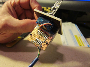
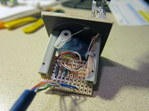
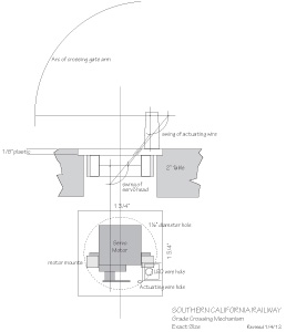
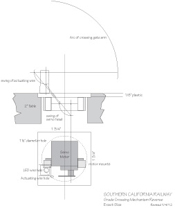
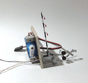
There are several crossings on the layout protected by flashers and gates. We chose the NJ International #1161 Crossing Gate Signal "A" Type with Black/White Gate as best representing the era we model. These were heavily modified. The actuating rod inside the base was disconnected and attached at the counterweight to give a much longer throw. The cast on gate lights were ground off and replaced with red micro LEDs from Richmond Controls. These were attached using ACC and the fine wires bundled on the back side of the gate and passed through an enlarged opening the side of the base cabinet. In operation these wire have enough flex to move through this opening without damage.
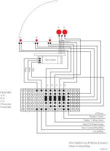
We use 9g servo motors to actuate the gates and designed the entire crossing gate unit to fit in a 3/4 inch hole in the layout with a cat5e cable plug attached. As with the CTC signals, the goal was to assemble the crossing signals and bench test them before installing them on the layout.
The servo motors are actuated by an Arduino, an inexpensive microcontroller which can be purchased pre-assembled on the internet. Marty Nile not only programmed the unit to actuate the gates and lights, but also to provide the sound of a crossing bell. Once tested, the gates were installed on the layout, plugged into the CMRI system and the scenery built up around them.
Documentation
- Southern California Railway CTC Operator's Manual
- Here is a video describing the procedure for programming the gate positions and speeds.
- Here is a web page describing the controller.
- C-MRI Code, version 1.44 (zipped)
- CTC Relay Source Code (zipped)
- CSRY Panel
- IOMBX - Indio
- IOMBX Layout 1
- IOMBX Layout 2
- IOMBX Layout 3
- IOMBX Layout 4
- IOMBX Layout 5
- IOMBX Layout 6
- SMINI - Basin
- SMINI - Encina
- SMINI - Esperanza
- SMINI - Valencia Tower
Home | Consultant | Books | Model Railroad
JohnSignor.com © 2026 John R. Signor. Written or verbal permission is required to reproduce any material contained in this website.
Website by Silver Rockets.
