The Southern California Railway
"From the Mountains to the Desert to the Sea."
Background | Concept | Construction | Wiring-Control | Signaling & CTC | Operations | Gallery
Wiring-Control
Control System
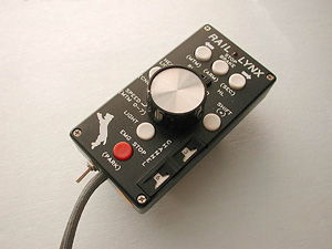
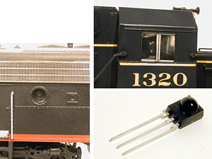
We use an infrared command control system supplied by Rail-Lynx. Rail-Lynx is a 255-channel infrared command control system which provides for cordless walk-around control with all data from the hand held unit being sent directly to the loco, with the track providing only DC power. The infrared sensors are mounted inside the locomotives, typically behind cab windows or portholes. MUing of locos is possible and locomotive addresses may be changed via the hand held controller. While Rail-Lynx does not support sound at present, we have found this to be a reliable, inexpensive and extremely simple system to use. All that is needed for a fully operational system is a transmitter and a sensor/receiver combination. No computer interface is required nor any of the many boosters, programming tracks, wireless controllers and other paraphernalia typically required for DCC, as no control signal passes through the rail.
Train in a Drawer
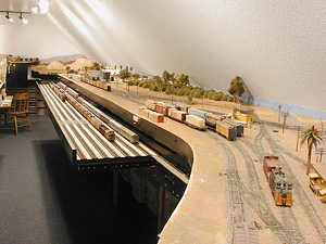
Over coffee one day Bruce Petty and I penciled an idea on a paper napkin which dispensed entirely with a staging yard with traditional ladder tracks and remote, difficult to reach, hidden switches. It was what amounted to a huge transfer table. Tracks could be longer, uniform in length, and there would be room for more of them.
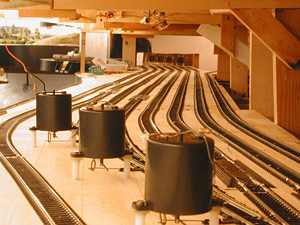
As built it is 16 feet by 18 inches underneath the layout on the east wall of the room. The table itself was made up from 5/8" cabinet grade 4x8 plywood sheets ripped length wise, trimmed and laid end-to-end. A 1x3 wood face plate was grooved to fit over the front edge of the plywood. This would provide rigidity, add a finishing touch and protect the trains on the tray. A sturdy gusset bolted in the middle allowed disassembly and movement of the various parts to the layout room.
Assembly was straightforward. I placed the two sections of the tray face down on the floor near the area where it was to be positioned, screwed the gusset in place, slid the face plate in position and secured it with screws. Four Accuride Model 3600 heavy duty, full extension, three member, low profile ball bearing drawer guides were acquired ( Accuride 12311 Shoemaker Ave, Santa Fe Springs, CA 90670 (562) 903-0200) and the cabinet member of each was mounted on 18" 2x2s and carefully bolted at 90 degrees to the face on the bottom of the tray. The guides were positioned 71/2," and approximately six feet, from each end. The overall assembly, with drawer guides attached, was then lifted up into place on the L girders. This was an awkward and somewhat heavy lift which required two people. The cabinet member of the guides were now bolted in turn to 2x3s which were squared up on the L girders. Once satisfied with the tray's position, the 2x3's were bolted to the L girders and final adjustments were made to make the table level.
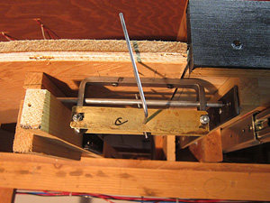
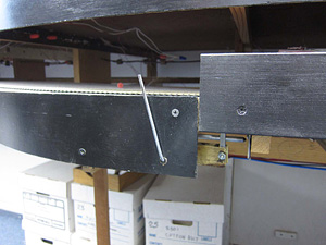
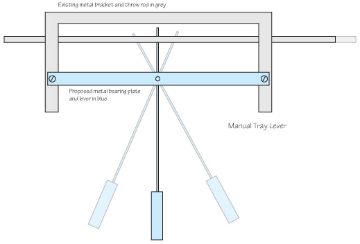
Positive positioning on each end is achieved by means of tapered 1/4" steel pins locking into holes drilled on flat indexing bars. 1/4" holes were drilled on two inch centers on 1/8" x 11/8" flat steel bars and bolted to 2x2's, one for each end of the tray. A tapered 1/4" steel rod, fitted in a U-shaped bracket, and operated manually, provides a positive lock at each end.
Once the indexing bars were in place, nine lengths of track, 16 feet long, were tacked down on two inch centers with track nails allowing enough rail to overhang the ends of the table to require trimming. I used Atlas Code 100 flex with rerailers near both ends of each track. Once in its final position, I laid track up to the edge of the moving tray and carefully trimmed the ends of each segment of track to provide close but adequate clearance.
In operation, a track is selected and the tray is pulled out manually until the approach track and selected track on the tray are lined up. The manual levers are thrown and the tapered pins move to lock the tray in position. Trains can now be driven onto or off the tray.
As built the tray can accommodate a total of approximately 288 50 foot cars.
East End Staging Yard Diode Matrix
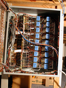
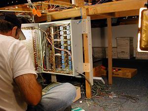
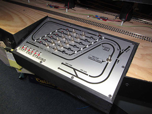
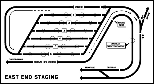
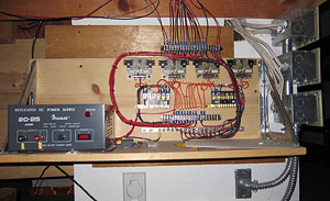
The East End Staging Yard complex is built inside a large return loop under the central peninsula. It has six tracks of equal length with power switches at each end. It is controlled by a diode matrix system with latching relays (Figure 1) designed and built by Rod Loder (Figure 2) which uses momentary contact toggle switches to set the route. Since this is a reversing section all staging tracks are isolated with floating polarity which is controlled automatically depending upon entrance and exit switch position. Power switches are moved by Switchmaster stall motors with Cherry E series snap action micro switches with extended actuating tab activated by the throw rod to show position (Figures 3 and 4). In operation, eastward trains move from L to K then enter the yard at switches A through E then exit westbound via switches F through J. The entire East End Staging Yard facility is on a separate circuit breaker. The system has been in operation since 2004 and performs flawlessly.
Wiring
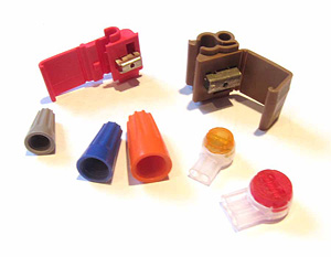
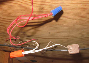
I was brought up in the Rod Loder school of bullet proof wiring. Power for the layout is supplied by a 20 amp commercial supply which feeds regulated 12 volt track power through five circuit breaker districts via 12 gauge solid copper wire buses that extend to every point on the layout. Rail joiners are for mechanical connections only. Every piece of track is hard wired with 18 gauge solid copper wire soldered to the web of the rail. All under table connections are made with 3M Scotch-Lock 567 and 568 "suitcase" connectors and in some cases wire nuts. No soldering was done under the table. All electrical gaps in the rail are filled with strip plastic and ACC glued in place.
Home | Consultant | Books | Model Railroad
JohnSignor.com © 2026 John R. Signor. Written or verbal permission is required to reproduce any material contained in this website.
Website by Silver Rockets.
